Step4: Bringing It All Back Home
At this stage, both the V1 and the GPS are hardwired and all the cable connections may extend outside the shift boot.
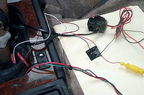
In this photo, you can see how all the cables are connected for power and ground.
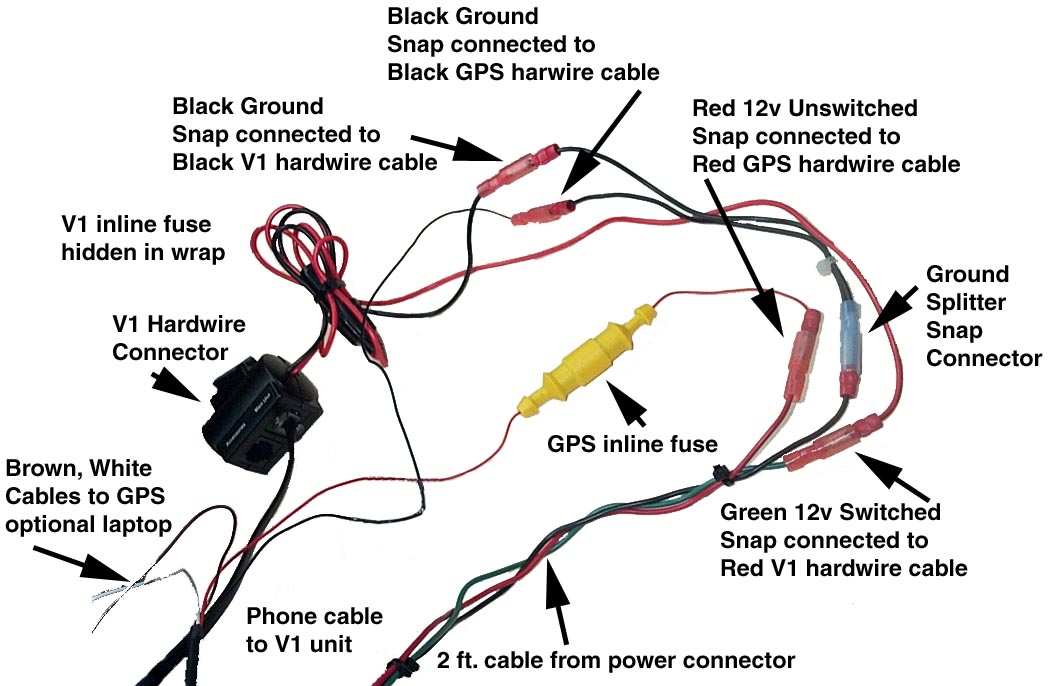
Red 12v unswitched power snap connected to Red GPS hardwire cable
Green 12v switched power snap connected to Red V1 hardwire cable
Black Ground snap connected to Black GPS hardwire
Black Ground snap connected to V1 hardwire cable
Flat black V1 cable plugged into MAIN jack on V1 hardwire box
White GPS hardwire cable not used at this time
Brown GPS hardwire cable not used at this time
Carefully wrap electrical tape over all snap connectors. Be certain that any unused connectors are wrapped. Wire tie the cables together and reinsert back into the shift boot, running the cable along the passenger side and placing the V1 hardwire box and all connectors neatly under the HVAC, in front of the shift boot.

Once the wires are out of the way, reinstall the rubber shifter insert and replace the shift boot. Replace the parking brake boot.
In Closing:
After I had completed my hardwiring, Rachel found an elegant way to run the V1 cable without removing the glovebox. If I had to do it again, I would follow her lead and route the cable through the ductwork.
I would also use a yellow cable for switched power instead of green. No real reason, except that yellow is a "hotter" color than green and cooler than red.
At some point I hope to attach a laptop data cable to the GPS hardwire in a way that will keep it out of sight when not in use.
If hardwired power is ever needed for additional devices, additional splitters could be added to the cables.
From Vince Parson's article: Finding Power in your Center Console
"The pins required for the connector are odd-sized. They're 0.098 inch pins. The common 0.093 inch pins won't stay in. The good news. You can get the correct size pins and even the mating connector free from AMP. Call (800) 522-6752 ask for some engineering samples. Ask for part numbers 1-828737-1 (the mating connector) and 927797-2 (the pin). I asked for 5 connectors and 20 pins, and they didn't bat an eye."
If you are installing an Ungo, I believe these pins are the correct size for mating with the siren connector under the hood and below the dash.
Other MZ3net articles on hardwiring:
Cellphone and Radar Detector Power, Another Way
Many thanks to my friend Roll for his assistance, Lisa and Bill for their garage and special thanks to Rachel for bringing it all together.